
Connecting the Control Unit - Turf Tank One+
Disconnecting and Reconnecting the Control Unit Cables
The cables that connect to the Robot’s Control Unit determine how–and whether–the Robot operates.
There are four cables connected to the Control Unit. These cables are:
The Power cable. Gray.
Larger connector than the others.
The connector has a 4-pin female plug with a cross pattern separating the pins.
Two ends of the cross pattern have slight J-shaped curves and will only insert one way.
It connects to the first port closest to the Battery/Paint Compartment, the largest port on the Control Unit.
The Rover cable. Black.
The plug has a 6-pin or 8-pin connector.
The receptor has 8 slots for the pins.
There is a semicircular notch in the outer ring of the receptor at the top of the port.
It connects to the second port from the Battery/Paint Compartment.
The ID Tag cable. Green.
This is a 4-pin cable.
The receptor circle is flat at the top.
A small plastic alignment pin sticks up from the flat side.
It connects to the third port from the Battery/Paint compartment.
The CAN cable. Purple.
This is a double cable attached to a single 5-pin connector.
It is the last port from the Battery/Paint compartment.
There is a small semicircular notch in the receptor at the 11 o’clock position (see Fig. 2).
Fig. 1
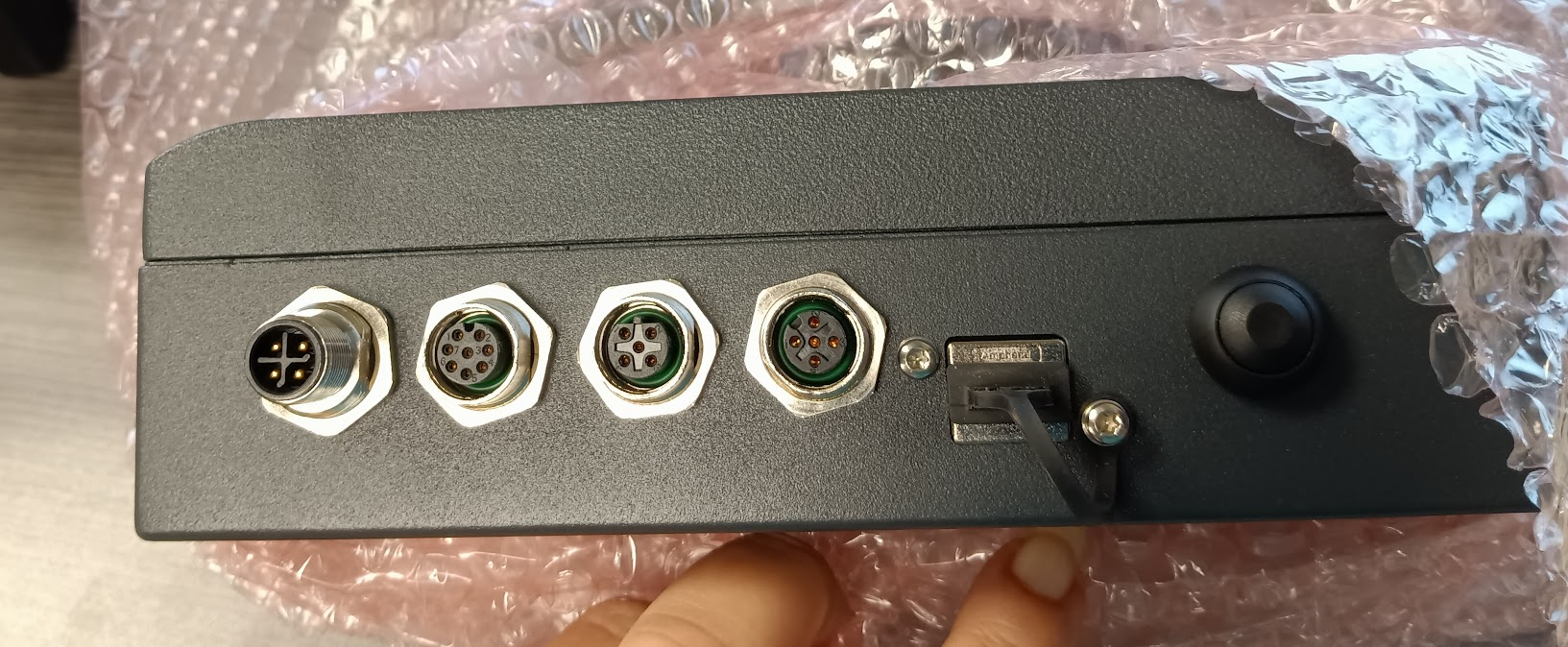
The ports, from L to R: Power, Rover, ID Tag, CAN
Fig. 2
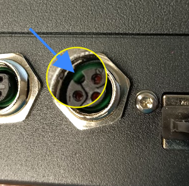
As with all the connections, it is essential to align the male pins with their female ports (or vice versa, as with the Power cable). The notch guides proper alignment.
The collars on the connectors screw onto the outer housings of the ports. The collars are designed to screw straight on, showing no threading (perhaps one thread will remain visible) when properly connected.
The collars can be finger tightened only so far. They must be tightened the rest of the way using pliers--needle nose or similarly thin types.
Fig. 3 and Fig. 4
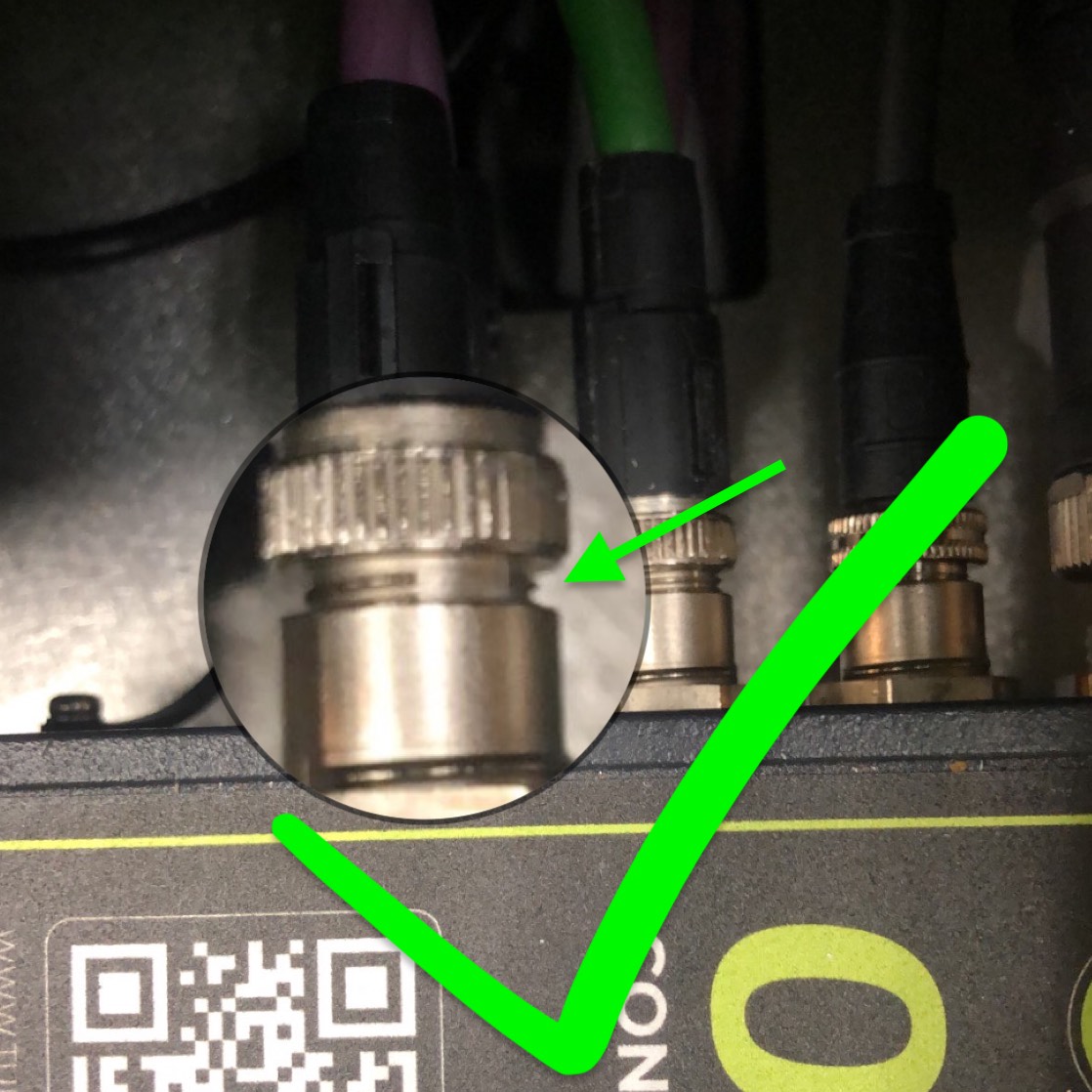
Proper connection: Only one thread showing.
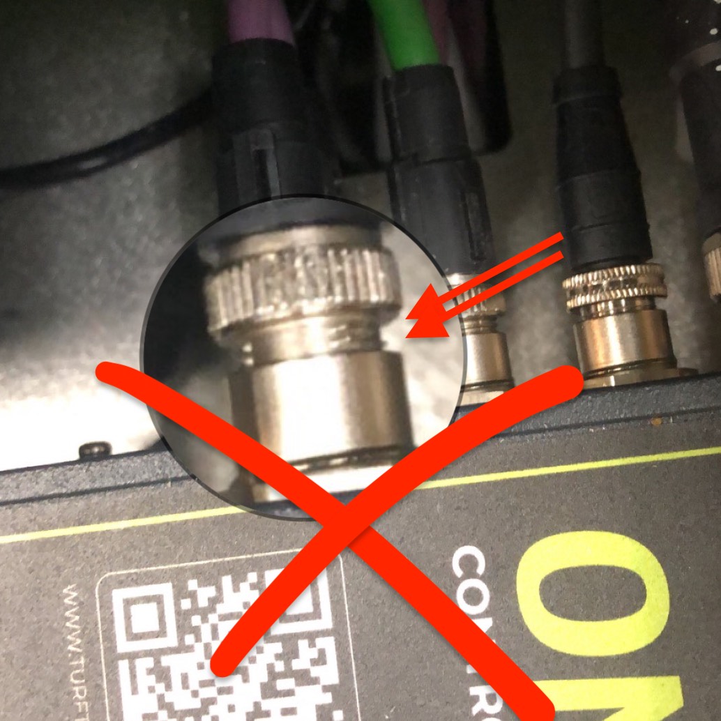
Improper connection: Multiple threads showing.
If any of the cables are not connected properly, the Robot will not operate. The most commonly misconnected cable is the CAN cable, the purple double cable with the single connector.
Step By Step Guide to Disconnecting and Reconnecting the CAN cable.
Using needle nose or similar pliers, loosen the collar of the connector on the purple double cable.
Once it is loose enough, you can use your fingers to unscrew it the rest of the way.
Examine the pins inside the cable connector.
If any pins are bent, gently coax them back into alignment.
Carefully re-seat the cable connector onto the port. Take care to angle the small semicircular part of the plug to the 11 o’clock position to match the receptor.
Make sure to keep the connector as straight as possible while screwing the collar back on with your fingers. It is easy to misalign the collar and the connection threads.
Double check before you tighten the collar down with the pliers that the collar is screwed on straight.
Tighten the collar to connector with needle nose or similar pliers. No threads should be showing (or one at most).

As always, take care when using pliers on the connector collar. The metal on the collar is soft and pliers can easily strip the outer grip ridges or deform its shape.