
Replace the Actuator (Turf Tank One and One+)
The actuator raises and lowers the spray discs. If the actuator isn’t working, check both the actuator relay (Q1 in the fuse box diagram below) and the actuator 3 amp fuse (F6 in the fuse box diagram below).
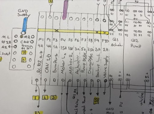
If both of those components are fine, you can replace the actuator itself.
Required Tools
Screwdriver (flat or Philips?) | Small needle nose pliers |
Small screwdriver or other small pointy tool | Two 13 mm wrenches |
Remove the Actuator
Remove the cover of the fuse box on the back of the Robot with a screwdriver exposing all the wires.
Take out the red and black wires labeled ACT +/-, located on the right side of the circuit board (from the perspective behind the Robot).
Note the position of the red and black wires (red = left, black = right).
Use a small-tipped screwdriver or other small tool to depress the orange tab that frees the wires.
Unscrew the appropriate gray cap on the back of the fuse box (under the back metal panel) to pull the wire through the back of the box.
Pull the wire out through the group of cables along the left side of the Robot. You will need to remove the plastic covers over the cables.
The cable will run along the cable guide to the front of the controller, then feed down into the square access hole next to the controller.
Remove the top nut on the right side of the actuator with two 13 mm wrenches. One to hold the middle nut in place and the other to remove the top nut.
Remove the middle nut and the bolt, freeing the actuator from the disc arm plate.
Remove the cotter key (on the left in the picture below) with needle nosepliers:
Straighten or cut the ends of the wire.
Pull the wire out of the hole.
Remove the bolt by pulling it out and up (no tools).
Install the New Actuator
Replace the actuator by following the above steps in reverse order.
Slide in the bolt on the left side of the actuator (in picture above).
Insert the cotter key, bending the ends with needle nose pliers.
Attach the nuts to the right side bolt, making sure there is a middle nut and top nut with the disc arm plate between them
Slide the new cable up through the square access port.
Feed the cable through the cable guide along the left side of the Robot.
Feed the wire through the back of the fuse box.
Screw on the plastic cap holding the wire in place.
Depress the orange tabs to insert the red (left, as viewed from the rear) and black (right) wires into the appropriate holes.